Change
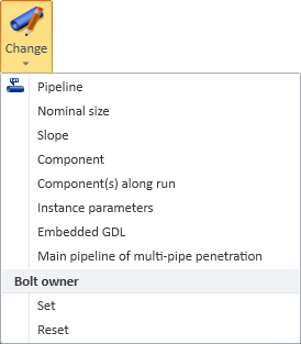
On the Piping tab, in the Edit group, the Change menu includes the following tools for making changes to piping-related parts.
Pipeline
You can change the pipeline that a set of piping parts is using. If the new pipeline uses different specifications, you must select which specification each part is to use after the change.
Prerequisites
-
The parts can be mapped to a specification in the target line. Otherwise, they must be marked as out-of-spec parts, if they are allowed in the new line.
Do the following:
-
On the Piping tab, in the Edit group, select Change > Pipeline.
-
Select the required piping parts from the model, and press Enter to accept the set.
The Select Pipeline dialog opens.
-
Select the line to use and click OK.
You can use the Search field to find the required line. Also regular expressions are supported.
 Show/hide details
-
The columns that are searched are predefined. Note that the search string can also be found from a column that is not currently visible: click Columns to define which columns to show.
-
The search string can be found from any part of the target string, and the search is not case-sensitive.
Search string…
Finds…
line
strings that contain LINE, such as 'MyLine-01'
-
You can use a dot to represent a single required character.
Search string…
Finds…
....line-01
strings where LINE-01 is preceded by at least four characters, such as 'AA_MyLine-01'
-
You can use advanced regular expressions if you add R: to the beginning of the search string.
Search string…
Finds…
R:[ad]
strings that contain A or D, such as 'DIN_H2A'
R:[a-d]
strings that contain A, B, C or D, such as 'CW-001'
R:^k
strings that start with K, such as 'K51'
R:[\s]
(or just R: followed by one space character)
strings that contain a whitespace character, such as 'My Line 01'
-
-
If any part in the set uses a specification that cannot be directly mapped to a specification in the target line, the Spec mapping issues… dialog opens, listing the differences.
Those parts whose specification has the same name and same position (1st–5th) in the new line are automatically mapped; they are not shown unless you select the Show all parts option.
If parts are not mapped simply because the specification has a different position in the new line, you can select the Map specification via name option to allow the program to find the specification from a different position.
You can use the following tools to get more information about an individual part:
-
Query – Opens the Object properties dialog for the selected part.
-
Browse – Highlights the part in the 3D model and connects the cursor to it with a rubber band line. Press Esc to return to the mapping issues dialog.
-
Locate – Allows you to pick a part from the 3D model and then selects that part in the mapping issues list.
Then, if you want to continue the change operation, click Change.
-
-
If any part in the set belongs to an isometric group, you are prompted whether to remove the parts from isometric groups.
-
Select Yes to assign the parts to the new line and to remove them from isometric groups.
-
Select No to assign the parts to the new line and the new line to the existing isometric group.
-
Select Cancel to return to the mapping issues dialog.
-
-
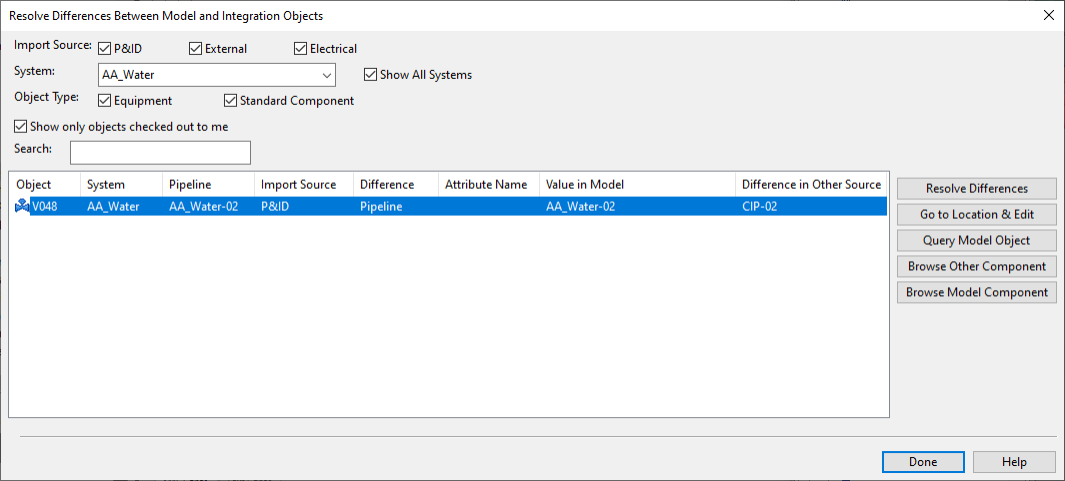
If any part in the set is linked to an integration object and there are differences in the data, the Resolve Differences Between Model and Integration Objects dialog opens, listing the differences. For more details on this dialog, see Compare objects.
-
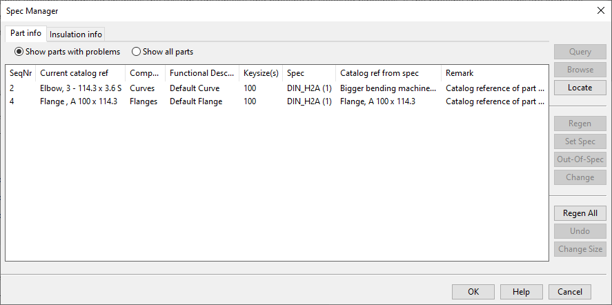
The Spec Manager dialog opens for defining the specification mappings. The dialog has two tabs: one for mapping the piping parts and another for mapping the insulation. On each tab, you can select Show parts with problems to see only the parts that have some issues.
You can use the following tools:
-
Regen – Regenerates the selected parts, using the piping and insulation specifications of the new line.
-
Set Spec – Opens a dialog for selecting a specification for the selected parts from the new line.
Note: You must select insulation specification separately, on the Insulation info tab.
-
Out-Of-Spec – Opens a dialog for confirming whether to mark the selected parts as out-of-spec parts, meaning that they keep their current catalog reference even if it is not supported by the specifications of the new line. (The operation fails if the new line does not allow out-of-spec parts.)
-
Change – Opens a dialog for changing the catalog reference of the part.
-
Regen All – Regenerates all the parts, using the piping and insulation specifications of the new line.
-
Undo – Reverts the changes you have made.
-
-
When all the parts have a suitable mapping and you have regenerated the parts, click OK to complete the operation.


Nominal size
You can change the nominal size of parts in a pipe run, one pipe run at a time. If the pipes have hole requests, the tool also tries to update the dimensions of the hole requests.
Regarding P&ID integration, the procedure is the same if the pipeline is only meant for modeling, i.e. the value of the attribute "Use In Diagram" is "Deny". If the pipeline is used also in P&ID ("Use In Diagram" is "Allow"), the nominal size is compared to the nominal size of the pipeline in the diagram.
Do the following:
-
On the Piping tab, in the Edit group, select Change > Nominal size.
-
Pick the first piping part to be changed, and accept the selection.
-
Pick the last piping part to be changed, and accept the selection.
The pipe run from the first whole pipe object to the last becomes selected, and the Change Nominal Sizes dialog opens.
-
Enter the new nominal size value, and click OK.
The pipe parts along the specified pipe run are regenerated, and the active work view shows the progress by highlighting the part that is being changed.
-
If you are prompted that the tool could not update all hole requests that are related to the changed objects, you must run the Update from trigger command in the Properties of Hole Request dialog of Hole Manager.

Slope
You can change the slope angle of pipe runs that are located in the XY plane. You can use this to add upward or downward sloping to a pipe or to level a pipe that is currently sloping. The program tries to accommodate the changes to the pipe run by adjusting straight pipes and flexible bends and moving Standard Components along the run, as required. The tool is able to turn, for example, a pipe run that has parts in the XY plane and parts that have a slant of 30 degrees into a single slope. If the pipes have hole requests, the tool also tries to update the location of the hole requests.
Tip: While routing a pipe, you can select a predefined slope ratio from the Slope context menu.
Do the following:
-
On the Piping tab, in the Edit group, select Change > Slope.
-
Select a set of connected piping parts that belong to the same pipe run and press Enter. The Slope Properties dialog opens.
-
Define the properties:
-
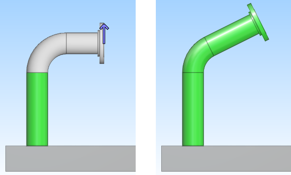
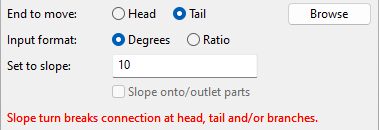
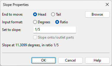
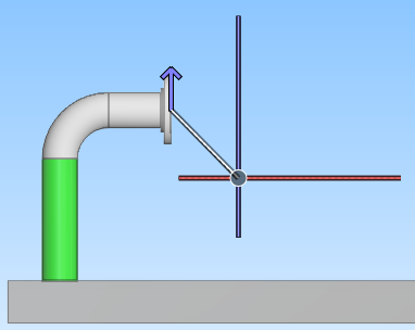
End to move – Select whether it is the Head or the Tail of the pipe that should move while the opposite end stays in place.
An arrow in the work view shows which end of the pipe is to be moved and to which direction (up/down). If you cannot see the arrow, you can click Browse and navigate to a better position; the work view displays a rubber band line that extends from the cursor to the pipe end that will move.
Then press Esc to return to the property dialog.
-
Input format – Select how to define the slope:
-
Degrees – Define the slope as the angle between the XY plane and the pipe (max ±45).
-
Ratio – Define the slope as the ratio of vertical change to horizontal change (max ±1).
-
-
Set to slope – Define the amount of slant the pipe is to have. Negative value creates downward slope, positive value creates upward slope, and 0 aligns the pipe with the XY plane.
The dialog shows the resulting slope value. If the change would cause any part to be disconnected from the adjacent part, the property dialog shows a red warning and you must decide whether to accept the result or try to change the slope properties so that the parts would not get disconnected.
-
Slope onto/outlet parts – This option enables slope to be applied to onto-line and outlet parts that follow the pipe to its new location. If not selected, onto-line and outlet parts move but their slope remains unchanged.
Note: You cannot set slope if a branch connection such as a welding nipple has been inserted as a piping part, whereas inserting a branch part as a Standard Component allows slope to be set.
-
-
Click OK to apply the change to the pipe run.
-
If you are prompted that the tool could not update all hole requests that are related to the changed objects, you must run the Update from trigger command in the Properties of Hole Request dialog of Hole Manager.
Note: Administrator can enable slope checks in Isometric Checks and Spool Checks.
Component
You can change the catalog reference of a pipe part or standard component. The geometry type of the new part must be the same as that of the old part. If the components have hole requests, the tool also tries to update the dimensions of the hole requests.
Example use cases:
- You want to change a slip-on flange to a neck flange, or use elbows instead of a bending machine for curves.
- P&ID designer has changed the valve type of a valve already inserted to the model, and you have to update it in the model.
Note: If you want to change several same type of parts in a pipe run, use the command Component(s) Along Run instead.
Do the following:
-
On the Piping tab, in the Edit group, select Change > Component.
-
Pick the component you want to change, and accept the selection.
-
In the Select Component dialog, select the new component, and click OK.
If P&ID integration is in use and the new component has been defined in P&ID, the new component is automatically selected.
-
If you are prompted that the tool could not update all hole requests that are related to the changed objects, you must run the Update from trigger command in the Properties of Hole Request dialog of Hole Manager.
Component(s) along run
You can change the catalog reference of several pipe parts or standard components along a pipe run. The first part you pick with this tool determines the type of the part—if you want to change valve components along a pipe run, then the first part you pick should be a valve (and not, for example, a straight piping part). If the pipes have hole requests, the tool also tries to update the dimensions of the hole requests.
Do the following:
-
On the Piping tab, in the Edit group, select Change > Component(s) along run.
-
Pick the first part to be changed and press Enter to accept the selection.
-
Pick the last part to be changed and press Enter to accept the selection. The Select Component dialog opens.
-
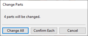
Select the replacement part and click OK. The parts to be changed are highlighted in the model and the Change Parts dialog opens, displaying how many parts can be changed.
-
Select how to proceed:
-
Change All – Select this option to change all the parts and complete the operation.
-
Confirm Each – Select this option if you want to accept or reject each change separately.
-
Cancel – Cancels the operation.
-
-
If you selected to confirm each change, the first part to be changed is highlighted and you are prompted to click either Yes to replace the part or No to keep the existing part. Then the next part is highlighted and you can continue in the same way, until all the parts have been processed.
-
If you are prompted that the tool could not update all hole requests that are related to the changed objects, you must run the Update from trigger command in the Properties of Hole Request dialog of Hole Manager.
-
Press Enter if you want to activate the tool again and change parts in this or another pipe run.
Replace pipe with parts
You can replace a straight, untrimmed piping part (DM_GT_2P) with fixed-length parts. The tool inserts as many fixed-length parts as possible to fill the gap. The insertion process will stop if the next part would replace the anchor node of a branch.
Do the following:
-
On the Piping tab, in the Edit group, select Change > Replace pipe with parts.
-
Pick a straight piping part, and press Enter.
-
The tool suggests starting the process from the first node; press Space if you wish to select another node instead. Press Enter to accept the selection.
-
In the Select Component dialog, select the component to use, and click OK.
Instance parameters
You can change the instance parameters of standard components that are based on a component model (GDL) which uses instance parameters. If the components have hole requests, the tool also tries to update the dimensions of the hole requests.
Do the following:
-
On the Piping tab, in the Edit group, select Change > Instance parameters.
-
Pick the pipe component whose instance parameters you want to edit, and accept the selection. The Edit Instance Parameters dialog opens.
-
Edit the parameter values as required, and then click Evaluate GDL to test the effect of the new values in the active view. Default restores the default instance parameter values.
-
Click OK to accept the changes.
-
If you are prompted that the tool could not update all hole requests that are related to the changed objects, you must run the Update from trigger command in the Properties of Hole Request dialog of Hole Manager.

Embedded GDL
You can open the embedded GDL of a Standard Component for editing in the Component Modeller application.
You can use this, for example, to edit a component model that has been imported with the 3D-Import Manager tool or to edit a pipe support that has been created with LISEGA LICAD integration.
Important: The changes will be lost if you later re-create/re-import the embedded GDL.
Do the following:
-
On the Piping tab, in the Edit group, select Change > Embedded GDL.
-
Select the model object and press Enter. The Component Modeller opens.
-
Make the required changes and save the component model.
-
Exit the Component Modeller. The edited Standard Component is shown in Plant Modeller.
Main pipeline of multi-pipe penetration
You can set an existing multi-pipe penetration to be assigned to a main pipeline either automatically or manually. Note that the name of a penetration object contains the name of the pipeline it is assigned to, so changing the line assignment also changes the penetration's name.
Do the following:
-
On the Piping tab, in the Edit group, select Change > Main pipeline of multi-pipe penetration.
-
Pick the multi-pipe penetration to be changed, and accept the selection.
The Select Main Pipeline for Multi-Pipe Penetration dialog opens.
-
Select either automatic or manual assignment, and then click OK.
- Main pipeline is selected automatically – If this option is selected, when the application needs to get information on the main pipeline of this multi-pipe penetration, it automatically selects the pipeline that has the largest nominal size.
- Select Pipeline – Select a specific pipeline from the menu to set it as the main pipeline of this multi-pipe penetration.

Bolt owner: Set
You can manually specify which side of a flange connection reserves the joint materials (bolts, nuts, washers, gasket) in the BOM.
The Set command adds the "Include bolt set" tag (ibo) with the value "Yes" to the pipe part, and the information will be included when generating material lists. If this tag is not set, then a default rule (based on directions) is used.

Do the following:
-
On the Piping tab, in the Edit group, select Change > Set.
-
Pick each pipe part you want to set as a bolt owner, and accept the selection.
Bolt owner: Reset
You can manually remove the "Include bolt set" tag from pipe parts that have it.
Do the following:
-
On the Piping tab, in the Edit group, select Change > Reset.
-
Pick each pipe part from which you want to remove bolt ownership, and accept the selection.